Overview - AHA Hydraulic
Air / Pneumatic Brakes
Advantages
- Highest torque in the smallest space
- Long life floating discs for low heat and extremely low neutral drag
- No special tools required for repair or installation of component
- Self-adjusting for wear
Operation
- Torque range 30 lb. ft.- 1,200 lb. ft.
- Wet or dry application
- Automatic wear compensation
- Stationary cylinder assembly
- No levers, cams, or highly stressed parts
Customization
- Custom designs and alterations available
Additional Information
OTHER CJM AIR / PNEUMATIC BRAKES
Connect With CJM
Multiple Disc Air / Pneumatic Brakes (AHA)
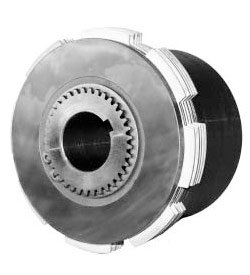
Carlyle Johnson's AHA model MAXITORQ® multiple disc spring set air / hydraulic / pneumatic brakes deliver more than ten times the torque of single disc pneumatic brakes of the same actuation and package size.
Featuring our patented MAXITORQ® floating disc principle, separator springs are utilized between brake discs, assuring fast disengagement with minimal drag, and minimal resultant heat when in neutral. Hardened steel inner friction discs are splined to the body for proper lug-load distribution. These discs operate against bronze-faced steel outer discs, providing long wear and smooth operation.
Our engineering department is available to assist you with your multiple disc air / hydraulic brake component. CJM can modify our standard AHA model pneumatic brakes to meet your needs, or custom design and manufacture a multiple disc brake to your exact specifications and operating requirements.
Features of AHA Pneumatic Brakes
CJM's multiple disc air / hydraulic pneumatic brakes are produced with a minimum of moving parts, which allows for quick and simple installation. A stationary cylinder assembly is mounted on deep-groove ball bearings to accommodate thrust loads, with quad-ring seals that assure maximum performance without leaking air or hydraulic fluid. Ample-sized ports and passages also provide fast piston action.
AHA model pneumatic brakes can be operated either dry or in oil. For wet applications (including oil mist, spray, splash or bath) the brake should be ordered without bearing shields. For dry applications AHA models are typically furnished with permanently lubricated ball bearings.
Specifications / Dimensions
| Model | Static Torque* (ft. lbs.) | Dynamic Torque* (ft. lbs.) | B10 Bearing Life**(hours) | A |
B |
Std. Bore |
| AHA-0015999 | 30 | 15 | 10,000 | 3.500 | 3.34375 | 3/4 or 7/8 |
| AHA-0025999 | 70 | 35 | 5,600 | 4.000 | 3.6250 | 1 or 1 1/8 |
| AHA-0050999 | 100 | 50 | 5,600 | 4.500 | 3.9375 | 1 1/4 or 1 3/8 |
| AHA-0100999 | 150 | 75 | 12,000 | 4.875 | 4.21875 | 1 1/2 or 1 5/8 |
| AHA-0200999 | 250 | 125 | 5,600 | 5.750 | 4.6250 | 1 3/4 or 1 7/8 |
| AHA-0400999 | 600 | 300 | 8,000 | 7.000 | 5.53125 | 2 or 2 1/4 |
| AHA-0800999 | 1,200+ | 600+ | 8,000+ | 9.500 | 6.37500 | 2 3/4 or 3 |
*Torque at 60 PSIG. Model refers to clutch number.
**Measured at 1800 RPM. B10 Bearing Life means that there is a 10% chance of bearing failure at the end of the stated period of time.
| Model | Keyway | C | D | G | NPT |
| AHA-0015999 | 3/16 x 3/32 | 3.5000 | .62500 | .9375 | .12500 |
| AHA-0025999 | 3/16 x 3/32 | 4.1875 | .68750 | .06250 | .12500 |
| AHA-0050999 | 1/4 x 1/8 | 4.6875 | .68750 | .06250 | .12500 |
| AHA-0100999 | 5/16 x 5/32 | 5.1875 | .87500 | .18750 | .12500 |
| AHA-0200999 | 3/8 x 3/16 | 6.7500 | .81250 | .18750 | .25000 |
| AHA-0400999 | 7/16 x 7/32 | 8.500 | 1.09375 | .12500 | .25000 |
| AHA-0800999 | 9/16 x 7/32 | 10.0000 | 1.18750 | .18750 | .25000 |
*Torque at 60 PSIG. St = Static. Dyn = Dynamic. Model refers to brake number.
**Measured at 1800 RPM. B10 Bearing Life means that there is a 10% chance of bearing failure at the end of the stated period of time.

| Internal Flange | ||||||||||
| Part # | Used With* | A |
B.C. B |
Screw Size | Holes | Pilot Dia. C |
D |
E |
F |
Slots |
| EMA-00325 106-300 | AHA-0015999 | 3.562 - 3.560 | 2.5670 - 2.5570 | 1/4 | 3 | 1.877 - 1.875 | 3.5000 | 1.0625 | .1875 | 8 |
| AHA-0025 106-300 | AHA-0025999 | 4.250 - 4.248 | 3.067 - 3.057 | 1/4 | 3 | 2.377 - 2.375 | 4.1875 | 1.2500 | .1875 | 8 |
| EMA-0425 106-300 | AHA-0050999 | 4.750 - 4.748 | 3.630 - 3.620 | 1/4 | 3 | 2.517 - 2.515 | 4.6875 | 1.2500 | .1875 | 8 |
| EMA-0475 106-300 | AHA-0100999 | 5.250 - 5.248 | 3.942 - 3.932 | 5/16 | 3 | 2.517 - 2.515 | 5.1875 | 1.3750 | .2500 | 8 |
| EMA-0625 106-300 | AHA-0200999 | 6.812 - 6.810 | 5.317 - 5.307 | 3/8 | 4 | 3.767 - 3.765 | 6.7500 | 1.6562 | .3125 | 8 |
| AHA-0400 106-300 | AHA-0400999 | 8.562 - 8.560 | 6.255 - 6.245 | 1/2 | 4 | 4.877 - 4.875 | 8.5000 | 1.9375 | .3125 | 12 |
| AHA-0800 106-300 | AHA-0800999 | 10.062 - 10.060 | 8.067 - 8.057 | 3/8 | 6 | 5.517 - 5.515 | 10.0000 | 2.0625 | .3125 | 12 |
*"Used with" refers to brake number.
| External Flange | ||||||||||
| Part # | Used With | A |
B.C. B |
Screw Size | Holes | Pilot Dia. C |
D |
E |
F |
Slots |
| EMA-00325 106-200 | AHA-0015999 | 4.625 - 4.623 | 4.130 - 4.120 | 1/4 | 3 | 3.300 - 3.298 | 3.5000 | 1.0625 | .2500 | 8 |
| AHA-0025 106-200 | AHA-0025999 | 5.625 - 5.623 | 4.880 - 4.870 | 1/4 | 3 | 3.814 - 3.812 | 4.1875 | 1.1875 | .2500 | 8 |
| EMA-0425 106-200 | AHA-0050999 | 6.125 - 6.123 | 5.380 - 5.370 | 1/4 | 4 | 4.314 - 4.312 | 4.6875 | 1.2500 | .2500 | 8 |
| EMA-0475 106-200 | AHA-0100999 | 6.875 - 6.873 | 6.005 - 5.995 | 5/16 | 4 | 4.814 - 4.812 | 5.1875 | 1.3750 | .2500 | 8 |
| EMA-0625 106-200 | AHA-0200999 | 8.500 - 8.498 | 7.692 - 7.682 | 3/8 | 4 | 6.377 - 6.375 | 6.7500 | 1.6562 | .3125 | 8 |
| AHA-0400 106-200 | AHA-0400999 | 10.625 - 10.623 | 9.630 - 9.620 | 1/2 | 4 | 8.095 - 8.093 | 8.5000 | 1.9375 | .3125 | 12 |
| AHA-0800 106-200 | AHA-0800999 | 12.250 - 12.248 | 11.130 - 11.120 | 3/8 | 6 | 9.533 - 9.531 | 10.0000 | 2.0625 | .3125 | 12 |
