 Menu
MenuIndustrial Clutch and Brake Selection General Guidelines
1. Determining the Size of a Clutch or Brake
To determine the appropriate size of a clutch or brake it is first necessary to determine what operational specifications are required. Those specifications include time, rotational speed, inertia load, the driving device, the driven elements, and the cycle rates. These operational specifications are evaluated through the use of a series of equations.
Frequently, the results of these equations will result in different clutch/brake selection values. For example, a clutch may be capable of providing adequate torque handling capacity for a system, but the cycle rate creates a heat load higher than the device can dissipate, in which case a larger clutch must be used in the application. In addition, there are external environmental variables which may influence the selection criteria. Is the device in an enclosed area where heat build-up could be a problem? Is the clutch or brake being run dry or in oil? What friction materials are available for the particular application being designed?
All of these variables must be carefully evaluated prior to final device selection. We recommend that you contact Carlyle Johnson for a review of your application prior to making a final selection. Our engineering expertise is always available to you for technical assistance.
1.1 Torque Based on the Drive and Driven Elements of a System
If you know the size of the driving device (such as an electric motor), the dynamic torque required can be calculated using the formula:

Sample Calculation: Torque output of a HP motor at 1,800 RPM with a clutch attached directly to the motor shaft:
Note that the above calculation does not address the type of driven element or the environment which the brake or clutch will see in operation.
The safety factor (K1) used in the sample calculation is 1.0, suitable for a standard AC electric motor. However other oscillating or pulsed loads on the clutch output, or inherent torsional loading on the clutch input, would require a different factor.
1.2 Torque based on Inertia and Time
If you know the inertia load of the system, the speed at which the clutch or brake is operating, and the time allowed to accelerate the load from zero up to the full speed (or in the case of a brake to stop the load from full speed), then you can determine the torque required using the following formula:
Sample Calculation: Torque required to accelerate an inertia load of 5 lb ft. from rest to 1,800 RPM in 0.5 seconds:
Start with a rough approximation of the dynamic torque, using the formula ((5 * 1,800) / (308) / .5)) = 58.44 lb ft. In the case of an electrically actuated clutch, the proper selection would be a model EMA0475, based on the table "Mechanical Data" found in Technical Bulletin 98, "Design Guidelines – Model EMA". (please contact CJM for our design guideline documentation). For other methods of actuation, refer to:
- electric clutch and brake actuation
- mechanical clutch and brake actuation
- hydraulic / pneumatic / air clutch and brake actuation
In this example, the EMA0475 with a dynamic torque rating of 75lb ft. is indeed the appropriate selection for an electrically actuated clutch.
1.3 Thermal Requirements
The above example must finally be tested against the heat load capacity of the selected device. Regardless of the torque requirements of the clutch or brake, the thermal capacity must be reviewed, to ensure that it does not overheat. The thermal loading of the clutch or brake is a direct result of the inertia, the speed and the cycle (on/off) rate.
These will further be influenced by the type of actuation (electrical, mechanical, hydraulic, or pneumatic), the type of friction element used (steel, bronze, synthetic kevlar, etc.) and the physical size of the clutch or brake.
The thermal loading can be calculated using the formula below:
Sample Calculation: Using the data from Section 2.1, determine the heat load with a cycle rate of 4 engagements per minute:
Again using the example of EMA0475 electrically actuated clutch , the resulting heat dissipation rate of 13.5 BTU/minute is insufficient to this application. If an electrical EMA-type clutch is desired, the larger EMA0625 with a heat dissipation rate of 20.5 BTU/minute would be required for this application.
There are additional external considerations for thermal capacity of a clutch or brake. External environment, operating conditions, and method of actuation will all play a role. It is important that our engineering staff be consulted before final selection is made.
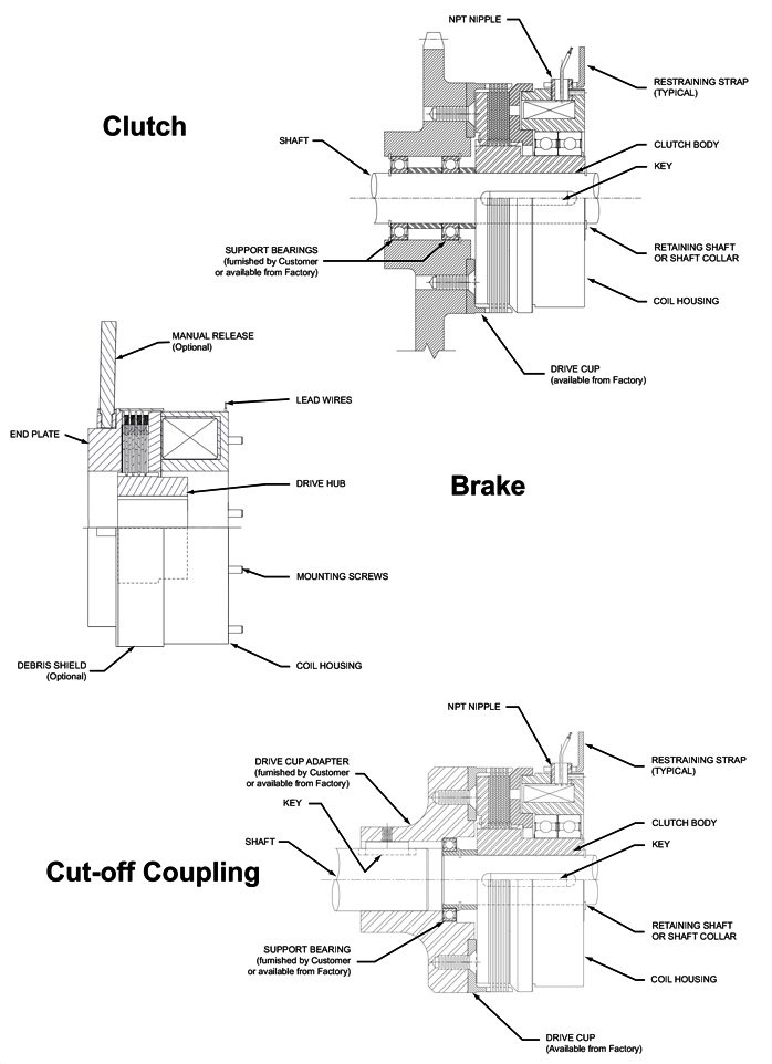
2. Alignment
The drive cup and the clutch or brake body must be held within .005 TIR when mounted. One design approach which will assure this concentricity is the use of an alignment bearing. The bearing and drive cup adapter or ring type drive cup are supplied by the customer or are available from Carlyle Johnson as an optional accessory: they are not included in the standard catalog clutch or brake configuration.
Tolerances on axial position by model are shown in the application literature.
If an alignment bearing is not used, care must be taken during design to maintain both the cup-to-housing dimension, as well as their concentricity and angular displacement.
Formula 1
Torque Calculation for Electric Motors
(Based on HP and RPM)
Formula 2
Horsepower of Rotating Objects
Formula 3
Horsepower of Objects in Linear Motion
Formula 4
Inertia of Bars, Shafts, or Discs
Weight Factor per inch of Various Materials (lbs)
| Steel Rubber Nylon Aluminum Bronze Cast Iron |
f= .890 f= .108 f= .161 f= .310 f= 1.010 f= .821 |
To Calculate the Inertia per Inch of Length for a Hollow Cylinder:
Subtract the WR2 of the I.D. from the WR2 of the O.D.
Formula 5
Reflected Inertia
Reflected Inertia (Rotating devices)
Inertia calculations used to determine the proper size for a clutch or brake must take into account the ratio of the speed (in RPM) of the clutch and the speed (in RPM) of the other elements in the system. While horsepower is essentially unchanged throughout the system, inertia scales up or down proportionally in relation to
Reflected Inertia (Linear devices)
Inertia calculations used to determine the proper size for a clutch or brake must take into account the load presented to the clutch from any linear devices being driven (such as a conveyor). This load can be reduced to an equivalent inertia value using the formula below. The critical information which must be determined is (1) the weight of the load; and (2) the diameter of the driving pulley, sprocket, gear, or drum.
Using the rotating device formula above, the inertia at the clutch can be calculated:
Disclaimer
The formulas and figures in these guidelines are believed to be accurate; however they are not guaranteed. We recommend you contact our engineering staff to discuss your application prior to ordering a clutch or brake. We will be happy to work with you in properly sizing a clutch, brake or accessory.More Information
Download Design Guidelines (PDF)
Require additional information or assistance? Please don't hesitate to contact our main office at:
- 860-643-1531 ext 116
- info@cjmco.com


